


What L298 Motor Driver IC can do and How it Works
A monolithic chip known as the L298 Motor Driver IC is utilized in motor driver modules to regulate the speed of DC motors. While the L298 remains a commonly used choice, alternatives such as the L293D and L2938N are increasingly prevalent. Typically employed in RC cars and autonomous robots, this IC receives input from controllers like Arduino.
The logic input serves to dictate the motor's direction, linked to the motor driver IC within the module. While the motor driver IC alone can control the motor, interfacing it with Arduino through the motor driver module streamlines the process. This discussion provides an overview of the L298 motor driver IC, along with its operation and applications.
What is L298 Motor Driver IC?
The L298 Motor Driver IC, a high-power variant of the L293 IC, serves as a dual full-bridge driver with robust current and voltage capabilities. Its primary function is to enable typical TTL logic levels to govern various inductive loads such as DC motors, solenoids, relays, and stepper motors. Acting as a small current amplifier, the motor driver utilizes a low current signal to generate a high current signal for driving electric motors.
Within the L298 IC, four distinct power amplifiers are integrated, with two amplifiers forming H-bridge A and the remaining two forming H-bridge B. One H-bridge facilitates polarity switching to regulate motor direction, while a pair of H-bridges is employed for controlling a bipolar stepper motor.
L298 Motor Driver IC
Each bridge within this IC incorporates two current sense pins, denoted as CSA and CSB, as well as enable pins, labeled as ENA and ENB. The current sense pins typically connect to the ground terminal, but they can also accommodate a low-value resistor, allowing their voltage reading to be proportional to the current. Similarly, the enable pins can be utilized to activate all the outputs simultaneously. All the enable and input pins in this IC operate with 5V TTL logic, facilitating easy interfacing with various types of microcontrollers.
L298 Motor Driver IC Pin Configuration
The pinout of the L298 dual full-bridge driver IC comprises 15 pins, each serving a specific function. Below is a breakdown of each pin, categorized by the dual bridges, H-bridge A and H-bridge B.
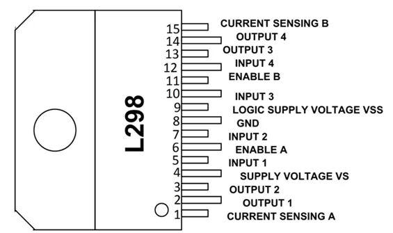
- Pin 1 (Current Sensing A): Used to regulate the current flow of the load.
- Pins 2 & 3 (Output 1 & 2): Output pins of H-bridge A, where current flows through the load, monitored at Pin 1.
- Pin 4 (VS): Voltage supply pin, connected to +5V.
- Pins 5 & 7 (Inputs): Control inputs of Bridge A, compatible with TTL.
- Pin 6 (Enable A): Enable input, TTL compatible.
- Pin 8 (GND): Ground pin.
- Pin 9 (Logic Voltage Supply): Provides voltage supply for the logic blocks.
- Pins 10 & 12 (Inputs 3 & 4): Control inputs of Bridge B, compatible with TTL.
- Pin 11 (Enable B): Enable input, TTL compatible.
- Pins 13 & 14 (Output 3 & 4): Output pins of H-bridge B, where current flows through the load, monitored at Pin 15.
Features & Technical Specifications:
The characteristics and technical specifications of the L298 IC are outlined below:
- Operating Voltage Range: Up to 46V.
- Maximum Continuous Current: Up to 4A.
- Low Saturation Voltage.
- Over-temperature Protection.
- Power Dissipation: 25W.
- Voltage Supply Range: +5V to +46V.
- Maximum Supply Voltage: 50V.
- Maximum Input and Enable Voltage: +7V.
- TTL-Compatible Control Inputs.
- Storage Temperature Range: -40°C to 150°C.
- Operating Temperature Range: -23°C to 130°C.
- Maximum Allowed Output Current: 3A per output.
How to Utilize the L298 Motor Driver IC/Circuit Diagram:
To comprehend the functionality of the L298 motor driver IC, consider the following basic circuit configuration. This circuit employs one of the H-bridges of the L298 IC. It can be set up with two push buttons designated as Q1 and Q2, which serve to manipulate the inputs of Bridge-A.
In this setup, the logic inputs are typically provided by a microprocessor or a microcontroller within application circuits. The four diodes integrated into the circuit act as flyback diodes, safeguarding the IC against voltage spikes.
The operation of Bridge-A primarily hinges on the enable pin. When the enable pin is pulled high using a resistor, Bridge-A becomes enabled and initiates operation. Conversely, when it is pulled to ground, it becomes disabled and ceases operation.
Upon establishing the circuit connection, we must engage the two buttons, namely Q1 and Q2, to alter the current flow between the two output pins, OUT1 and OUT2.
The logic control operates as follows:
- When push button Q1 is high and Q2 is low, it indicates forward current.
- When push button Q1 is low and Q2 is high, it signifies reverse current.
- When both push buttons are equal (Q1=Q2), it denotes a rapid motor stop.
Pressing the Q1 push button initiates current flow from Output to Output2, resulting in clockwise motor rotation. Conversely, pressing the Q2 push button causes current to flow from Output2 to Output1, leading to anti-clockwise motor rotation.
Simultaneously pressing or releasing both push buttons (Q1 & Q2) halts the motor instantaneously. Therefore, motor speed can be regulated using an L298 motor driver IC.
For further details, refer to the L298 Motor Driver IC Datasheet available at the provided link.
Where to Implement L298 Motor Driver IC/Applications:
The L298 motor driver IC finds application in various fields, including:
- Robotics and embedded systems.
- Situations where microcontrollers operate at low voltage and current, while motors require high voltage and current.
- Scenarios utilizing H-Bridge configurations.
- High-power applications.
- Instances necessitating current control and PWM-operable ICs.
- Situations where the control unit provides only TTL outputs.
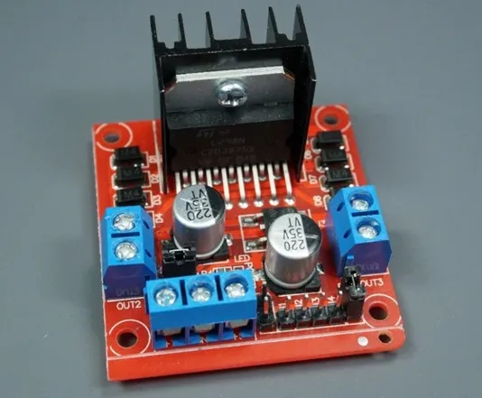
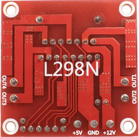
Board Features
Equipped with two 3.5mm pitch screw terminals, the L298N motor driver board accommodates a range of DC motors spanning from five to 35V, extending its utility to controlling relays and solenoids. Its integrated 5-V regulator supports logic circuits, and the board is readily available from various sources at affordable prices, with an optional 5 V power input.
L298N with DC Motor
The L298N with DC motor IC serves as a microcontroller capable of driving LEDs or other high-current loads, featuring inputs to control rotation direction and movement. With an onboard 5V regulator managing voltage and speed, precise motor control is achieved through L298N PWM signals.
Simple Implementation
Utilizing the L298N with a DC motor is straightforward, requiring a basic sketch that doesn't rely on external libraries. By defining corresponding Arduino Uno pins and invoking user-defined functions to manipulate speed and direction, the motor can be configured to operate seamlessly in any desired direction.
Comparing L293D and L298N Motor Drivers
If you're deliberating between the L293D and L298N for your Arduino project, let's dissect their functionalities to aid your decision-making process. Both shields serve as viable options for driving DC motors, bipolar stepping motors, and relays, with the capacity to control up to six motors. Here's an in-depth comparison of their features:
L293D Driver
Operating within a voltage range of 4.5V to 36V, the L293D driver caters to low-current applications. It incorporates a H-bridge configuration, allowing seamless control of standard DC motors via a logic chip or microcontroller. Moreover, it supports individual half-bridge controls, providing versatility in motor control scenarios.
L298N Driver
In contrast, the L298N driver boasts a wider voltage tolerance, capable of handling voltages up to 46V. This makes it ideal for high-current applications, offering robust performance in demanding environments. Like the L293D, it features a H-bridge design, enabling precise motor control through logic chips or microcontrollers. Additionally, it supports individual half-bridge controls, ensuring flexibility in motor manipulation.
Choosing the Right Driver
Ultimately, the choice between the L293D and L298N drivers hinges on the specific requirements of your project. If you're dealing with low-current applications and require a driver that operates within a moderate voltage range, the L293D may suffice. However, for high-current scenarios demanding greater voltage tolerance and rugged performance, the L298N emerges as the preferred option. Assess your project's needs carefully to determine which driver aligns best with your objectives.
In conclusion
The L298 Motor Driver IC serves to control motor direction and speed. Different motor driver ICs are available, differing based on factors such as maximum voltage supply, load voltage, maximum output current, rated power dissipation, and number of outputs. Generally, the L298 motor driver IC facilitates DC motor speed regulation and simplifies DC motor interfacing with a microcontroller.
Rlated Articles
Do ECM Motors Have Capacitors?
How Does a Single Phase Motor Work?
What is an Induction Motor :All You Need to Know
What L298 Motor Driver IC can do and How it Works


