


Operation & Fault Handling of High Voltage Switchgear Explained
This article provides a detailed introduction to the definition, types, and structure of high-voltage switchgear, as well as its main technical parameters. It also covers the procedures for energizing and de-energizing operations, as well as fault diagnosis and handling.
Basic Definitions of High Voltage Switchgear
High voltage switchgear refers to electrical products used in power generation, transmission, distribution, power conversion, and consumption systems for functions such as switching, control, or protection. These products operate at voltage levels ranging from 3.6 kV to 550 kV. They mainly include high voltage circuit breakers, high voltage isolating switches and grounding switches, high voltage load switches, high voltage automatic reclosers and sectionalizers, high voltage operating mechanisms, high voltage explosion-proof distribution devices, and high voltage switchgear. The high voltage switchgear manufacturing industry is an important part of the transmission and transformation equipment manufacturing industry and holds a very significant position in the entire power industry. Some people are willing to call high voltage switchgear "high voltage distribution cabinets," which are essentially the same thing.
Functions of High voltage switchgear
High voltage switchgear includes functions such as overhead line connection, cable connection, busbar connection, etc.
Applications of High voltage switchgear
It is mainly suitable for various places such as power plants, substations, power system substations, petrochemicals, metallurgical rolling mills, light industry textiles, factories and mines, residential communities, high-rise buildings, etc.
Composition of High voltage switchgear
The switchgear should meet the relevant requirements of the "standard for AC metal-enclosed switchgear." It consists of two main parts: the cabinet and the circuit breaker. The cabinet is composed of a housing, electrical components (including insulation components), various mechanisms, secondary terminals, and wiring.
Five Protections
- Prevent load closing: After the vacuum circuit breaker trolley in the high voltage switchgear is closed in the test position, the trolley circuit breaker cannot enter the working position.
- Prevent grounding wire closing: When the grounding knife inside the high voltage switchgear is in the closed position, the trolley circuit breaker cannot close.
- Prevent accidental entry into live intervals: When the vacuum circuit breaker in the high voltage switchgear is operating, the rear door of the cabinet is locked with the mechanical device on the grounding knife.
- Prevent live grounding wire closing: When the vacuum circuit breaker in the high voltage switchgear is closed, the grounding knife cannot be inserted.
- Prevent load knife switch pulling: During the operation and closing of the vacuum circuit breaker in the high voltage switchgear, the circuit breaker cannot exit the working position of the trolley.
Structural Composition of High voltage switchgear
It mainly consists of the cabinet, high voltage vacuum circuit breaker, energy storage mechanism, trolley, grounding knife switch, and comprehensive protection device.
Composition of High Voltage Switchgear:
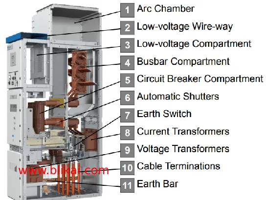
Cabinet
Pressed from iron plates, forming a closed structure with compartments such as instrument room, trolley room, cable room, busbar room, etc., separated by iron plates as shown in Figure 1. The instrument room is equipped with comprehensive protection devices, ammeters, voltmeters, and other equipment; the trolley room houses the trolley and high voltage vacuum circuit breaker; the busbar room accommodates three-phase busbars; the cable room is used for external connection of power cables.
High Voltage Vacuum Circuit Breaker
The so-called high voltage vacuum circuit breaker has its main contacts installed in a sealed vacuum chamber. When the contacts make or break, the arc is not aided by any gas, making it durable without burning out. Additionally, the base is made of insulating material to enhance the insulation performance of the vacuum switch, hence the name high voltage vacuum circuit breaker.
Trolley Mechanism
Mounting the high voltage vacuum circuit breaker on a trolley, which moves with the trolley. When the handle is rotated clockwise, the trolley enters the cabinet, carrying the vacuum circuit breaker into the high voltage circuit; when rotated counterclockwise, the trolley exits the cabinet, pulling the vacuum circuit breaker out of the high voltage circuit, as shown in Figure 2.
Energy Storage Mechanism
Driven by a small electric motor to store energy in springs, using the released energy from the springs to close the vacuum circuit breaker.
Grounding Knife Switch
It is a type of knife switch that acts on safety interlocking. When the grounding knife switch is closed, the high voltage cabinet door can be opened; otherwise, if the grounding knife switch is not closed, the high voltage cabinet door cannot be opened, serving as a safety interlock protection.
Comprehensive Protection Device
It is a type of microcomputer protector composed of a microprocessor, display screen, keypad, and peripheral circuits. It replaces the original relay protection circuits for overcurrent, overvoltage, time, etc. Input signals include current transformers, voltage transformers, zero-sequence current transformers, and switch signals. The keypad can be used to set current values, voltage values, tripping times, start times, etc. The display screen shows real-time data and participates in control, executing protection actions.
Classification by Form:
(1) According to the main wiring form of the switchgear, it can be divided into bridge-connected switchgear, single busbar switchgear, double busbar switchgear, single busbar sectionalized switchgear, double busbar with bypass busbar switchgear, and single busbar sectionalized with bypass busbar switchgear.
(2) According to the installation method of the circuit breaker, it can be divided into fixed switchgear and withdrawable (trolley-type) switchgear.
(3) According to the cabinet structure, it can be divided into metal-enclosed compartmentalized switchgear, metal-enclosed armored switchgear, and metal-enclosed box-type fixed switchgear.
(4) According to the position of the circuit breaker trolley installation, it can be divided into floor-mounted switchgear and center-mounted switchgear.
(5) According to the different internal insulation medium of the switchgear, it can be divided into air-insulated switchgear and SF6 gas-insulated switchgear.
Main Technical Parameters
Rated voltage, rated current, rated frequency, rated power frequency withstand voltage, rated lightning impulse withstand voltage.
Circuit breaker rated breaking current, rated closing peak current, rated short-time withstand current, rated peak withstand current.
Grounding switch rated closing peak current, rated short-time withstand current, rated peak withstand current.
Operating mechanism opening and closing coil rated voltage, DC resistance, power; energy storage motor rated voltage, power.
Cabinet protection level and compliance with national standards.
Energizing Procedure
Close all rear doors and rear covers, and lock them securely. The rear door can only be closed when the grounding switch is in the closed position.
Insert the operating handle of the grounding switch into the hexagonal hole at the lower right of the middle door, rotate counterclockwise to place the grounding switch in the open position. The interlocking plate at the operating hole automatically springs back to cover the hole, and the lower door of the cabinet is locked.
Push the service trolley into position and lock it. Push the trolley into the cabinet to position it in the isolating position. Manually insert the secondary plug and close the trolley room door.
Insert the circuit breaker trolley handle into the handle socket, rotate it clockwise for about 20 turns until the handle noticeably encounters resistance and clicks. Remove the handle. At this point, the trolley is in the working position, the secondary plug is locked, and the main circuit of the circuit breaker trolley is connected. Check relevant signals.
Operate the closing and opening switch on the control panel to close the circuit breaker and energize. At the same time, the green light on the control panel goes off, and the red light turns on, indicating successful closure.
De-energizing Procedure
Operate the closing and opening switch on the control panel to place the circuit breaker in the open position. At the same time, the red light on the control panel goes off, and the green light turns on, indicating successful opening.
Insert the circuit breaker trolley handle into the handle socket, rotate it clockwise for about 20 turns until the handle noticeably encounters resistance and clicks. Remove the handle. At this point, the trolley is in the testing position, the secondary plug lock is released, open the trolley room door, manually disconnect the secondary plug, and disconnect the main circuit of the trolley.
Push the service trolley into position and lock it, pull out the trolley to the service trolley, and open the service trolley.
Observe the live display or test for electricity. Only proceed if no electricity is detected.
Insert the operating handle of the grounding switch into the hexagonal hole at the lower right of the middle door, rotate clockwise to close the grounding switch. After confirming that the grounding switch is closed, open the lower door of the cabinet, and maintenance personnel can enter for maintenance and inspection.
Fault Diagnosis and Handling of Closure Failure
Closure failures can be categorized into electrical faults and mechanical faults. There are two closure methods: manual and electric. If manual closure is not possible, it is generally a mechanical fault. If manual closure is possible but electric closure is not, it is an electrical fault.
Protective Action
Before energizing the switch, if there is a fault in the circuit, the protective circuit activates the anti-jumping relay. The switch immediately trips after closing. Even if the transfer switch remains in the closed position, the switch will not repeatedly trip.
Protection Fault
Nowadays, high-voltage cabinets are equipped with five protection functions. It is required that the switch cannot be closed unless it is in the operating or testing position. In other words, if the position switch does not close, or if the electrically operated switch cannot close, it indicates a fault. This kind of fault is often encountered during the closure process. At this time, the operating or testing position indicator lights do not illuminate. Slightly moving the switch trolley to make the limit switch close will enable power transmission. If the offset distance of the limit switch is too large, it should be adjusted. In the JYN-type high-voltage cabinet, if the position switch cannot be moved outward, a V-shaped piece can be added to ensure reliable closure of the limit switch.
Electrical Interlocking Fault
In high-voltage systems, electrical interlocks are set up to ensure the reliable operation of the system. For example, in a single-bus sectionalized system with two incoming lines, it is required that only two out of three switches, including the two incoming line switches and the bus tie switch, can be closed. If all three switches are closed, there is a risk of reverse power transmission, leading to changes in short-circuit parameters and an increase in parallel short-circuit currents. The form of the interlocking circuit is shown in Figure 4. The interlocking circuit of the incoming line cabinet is connected in series with the normally closed contact of the bus tie cabinet, requiring that the incoming line cabinet can be closed only when the bus tie cabinet is in the open position. The interlocking circuit of the bus tie cabinet is connected in series with both a normally open and a normally closed contact of the two incoming line cabinets, and then connected in parallel. This ensures that the bus tie cabinet can only be energized when one incoming line cabinet is closed and the other is open. When the high-voltage cabinet cannot be closed electrically, the first consideration should be whether there is an electrical interlock. Manual closure should not be attempted blindly. Electrical interlocking faults are generally due to improper operation, which fails to meet the requirements for closure. For example, although the incoming line cabinet is open and closed separately, the trolley in the disconnector cabinet is pulled out and the plug is not inserted. If the interlocking circuit fails, the faulty part can be checked with a multimeter. Using red and green lights to determine auxiliary switch faults is simple and convenient but not very reliable. A multimeter can be used to check and confirm the fault. The maintenance method for auxiliary switches is to adjust the angle of the fixed flange and adjust the length of the connecting rod.
Control Circuit Open Circuit Fault
Damage to the control switch or line disconnection in the control circuit prevents the closing coil from being energized. In this case, there is no sound of the closing coil operating. Measure the voltage at both ends of the coil to check for an open circuit.
Closing Coil Fault
The burning of the closing coil is a short-circuit fault. At this time, there may be odors, smoke, blown fuses, etc. The closing coil is designed for short-term operation, and the energization time should not be too long. After a closure failure, the cause should be promptly investigated, and repeated attempts to close the coil should be avoided. Especially for the CD-type electromagnetic operating mechanism, repeated closure with high current can easily cause damage.
When troubleshooting faults where the high-voltage cabinet cannot be closed, the method of trial energizing is often used. This method can eliminate line faults (except for transformer temperature and gas faults), electrical interlock faults, and limit switch faults. The fault location can be basically determined to be inside the trolley. Therefore, during emergency handling, trial energizing in the testing position and using a spare trolley for power transmission can be employed. This method can achieve significant results and reduce downtime.
Related Articles
Principle, Structure and Fault Analysis of Centrifugal Switch
Switching Diodes: Definitions, Principles, Applications, and Future Trends


