


What is TL074 Operational Amplifier?
An operational amplifier, often abbreviated as op-amp, is a type of integrated circuit designed primarily to boost feeble electrical signals. Typically, an operational amplifier comprises two input terminals and a single output terminal. Its fundamental operation involves amplifying the input signal and producing a voltage differential between the two inputs. Various types of op-amp integrated circuits are readily accessible in the market, each tailored to specific requirements. This article provides an overview of the TL074 operational amplifier, elucidating its functionality alongside applications.
What is the TL074 Operational Amplifier?
The TL074 is a quad monolithic operational amplifier with JFET inputs, featuring four integrated Op-Amps. It incorporates high-voltage Bipolar Junction Transistors (BJTs) and Junction Field-Effect Transistors (JFETs). Furthermore, it boasts low input bias and bias currents, while exhibiting an exceptionally high slew rate.
The TL074 operational amplifier is highly recommended for audio pre-amplification due to its low harmonic distortion and noise levels. Importantly, it offers the capability to adjust input offset through specific circuits.
Moreover, internal frequency compensation is possible, and TL074 operation is characterized by being latch-up-free. Within the TL07X family, both the TL071 and TL072 are variants featuring single and dual operational amplifiers, respectively.
TL074 IC Pinout Overview
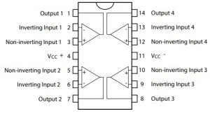
Below is the pin configuration of the TL074 operational amplifier, featuring a total of 14 pins. Each pin's function is elaborated upon for clarity:
1. Offset Null 1: Utilized for offset nulling or compensation fine-tuning in specific applications.
2. Inverting Input (A): Input terminal for the inverting signal of Operational Amplifier A.
3. Non-inverting Input (A): Input terminal for the non-inverting signal of Operational Amplifier A.
4. Negative Power Supply (V-) for Operational Amplifier A.
5. Offset Null 2: Additional pin designated for offset nulling or compensation adjustment in specialized circumstances.
6. Output (A): Output terminal for Operational Amplifier A.
7. Positive Power Supply (V+) for Operational Amplifier A.
8. Positive Power Supply (V+) for Operational Amplifiers B, C, and D.
9. Output (B): Output terminal for Operational Amplifier B.
10. Non-inverting Input (B): Input terminal for the non-inverting signal of Operational Amplifier B.
11. Inverting Input (B): Input terminal for the inverting signal of Operational Amplifier B.
12. Negative Power Supply (V-) for Operational Amplifiers B, C, and D.
13. Output (C): Output terminal for Operational Amplifier C.
14. Inverting Input (C): Input terminal for the inverting signal of Operational Amplifier C.
This pin configuration facilitates precise signal manipulation and control in diverse electronic applications, ensuring optimal functionality of the TL074 operational amplifier.
Characteristics & Technical Details
Here are the features and specifications of the TL074 operational amplifier:
- JFET Input Operational Amplifier with Quad Package Configuration
- Available in Various Packages: 14-pin PDIP, TSSOP, SO-14, with different models such as TL74AB, TL74A, TL74L & TL74AC
- Typical Operating Voltage: ±15V
- Output Short Circuit Protection
- Maximum Operating Voltage: 36V
- Input Bias Current: 65pA
- Maximum Transition Time/Propagation Delay (Pd): 29ns
- Common Mode Rejection Ratio (CMRR): 100dB
- Low-Level Input Voltage: 0.8V
- Input Offset Voltage: 10mV
- Input Bias Current: 200nA
- Input Offset Current: 100nA
- Supply Current: 2.5mA
- Slew Rate: 13V/µs
- Power Dissipation: 680mW
- Output Short Circuit Current: 60mA
- Differential Input Voltage: ±30V
- Input Common-Mode Voltage Range: -12V to +15V
- Large Signal Voltage Gain: 200V/mV
- Power Supply Rejection Ratio: 86dB
Equivalent Op-Amp models to the TL074 include LM324, TL072, and TL071, while alternative options encompass LM748, LM741C, LM741A, LM709C, MC1439, and LM201 LF351.
How to Utilize the TL074 Operational Amplifier?
To employ the TL074 operational amplifier (IC), adhere to the following steps:
1. Power Supply Connection: The TL074 requires two power supplies, with pins 4 and 11 designated for this purpose. Pin 4 is utilized for the positive power supply, while pin 11 is allocated for the negative power supply.
2. Input Configuration for Op-Amp 1: Provide the inverting input signal at pin 2 and the non-inverting input signal at pin 3 of the first operational amplifier. The output of the first op-amp can be accessed at pin 1.
3. Input Configuration for Op-Amp 2: For the second operational amplifier, input the inverting signal at pin 6 and the non-inverting signal at pin 5. The output of this op-amp is obtainable at pin 7.
4. Input Configuration for Op-Amp 3: Connect the inverting input signal to pin 9 and the non-inverting input signal to pin 10 of the third IC. The output of this operational amplifier is accessible at pin 8.
5. Input Configuration for Op-Amp 4: For the fourth operational amplifier, direct the inverting input signal to pin 13 and the non-inverting input signal to pin 12. The output of this op-amp can be retrieved at pin 14.
By adhering to these guidelines, users can effectively utilize the TL074 operational amplifier in various electronic applications.
How to Properly Terminate Unused Pins in TL074 Op-Amp?
In integrated circuits such as the TL074, which come in packages containing multiple op-amps, it's common to encounter situations where not all op-amps are utilized. In such cases, it's crucial to terminate the unused op-amp terminals adequately to prevent any adverse effects on circuit performance caused by the buildup of capacitance.
Since the operational amplifiers in use draw significant power, leaving unused op-amp terminals unterminated can lead to reduced design efficiency. Various methods exist for terminating an operational amplifier, depending on the specific circuit design. However, one commonly employed method is outlined below.
In the circuit configuration depicted above, the operational amplifier operates within a voltage range defined by Vdd and Vss. To terminate the unused op-amp, connect the inverting pin to the output pin, while the non-inverting pin can be connected to a stable voltage source.
The value of the stable voltage can vary, but it should fall within the voltage supply limits of the IC. Therefore, it's not mandatory to include two resistors, as any available voltage within that specific range from the above circuit can be effectively utilized to terminate the non-inverting pins of the op-amps.
Headphone Amplifier Circuit with TL074 Op-Amp
The versatile TL074 operational amplifier finds application in various circuit designs, including headphone amplifiers. In this particular circuit, the op-amp assumes a pivotal role in driving the headphone unit.
Constructed around a single TL074 IC and powered by a 9V battery, this headphone amplifier circuit delivers substantial power output. Theoretically, it boasts a peak power of up to 100 units (equivalent to 200 mW) into a 32-ohm load, achieved through a voltage gain of 7.6 times (or 17.6 dB).
Where to Employ the TL074 Operational Amplifier?
The TL074 operational amplifier integrates four individual amplifiers within a single IC package, offering versatility in various applications. A standout feature of the TL074 is its incorporation of high-voltage JFETs and BJTs, enhancing transistor performance with exceptionally high input impedance and minimal bias current.
Primarily, the TL074 finds widespread usage in audio preamplifiers due to its low harmonic distortion and noise characteristics, particularly advantageous when seeking an IC driven by JFETs and packaged in quad configuration.
The TL074 operational amplifier is well-suited for the following applications:
1. Circuits requiring high input impedance
2. Comparator circuits
3. Buffer applications
4. DC gain blocks
5. Voltage followers
6. Differentiators, integrators, summers, voltage followers, adders, etc.
7. Filter circuits
8. AC/DC converters
9. Oscillators
10. Unity gain inverting amplifiers
11. Half-wave rectifiers
12. Square wave generators
13. Power supplies
14. Bilateral current sources
15. Instrumentation amplifiers
16. Voltage comparators
These applications showcase the adaptability and utility of the TL074 operational amplifier across a wide range of electronic circuit designs.
Summary
This encapsulates the essence of the TL074 operational amplifier. It embodies a high-speed quad op-amp with JFET inputs, boasting notable features such as minimal input bias, a high slew rate, and low offset voltage and current. Available in diverse packages like DIP and SO, it caters to various application needs.
The TL074 shares a close kinship with the LM324 IC, both housing operational amplifiers and featuring similar pin configurations. However, their distinction lies in the TL074's integration of JFET technology. Now, onto your question: What function does the LM324 IC serve?


