


Resistor Transistor Logic (RTL): Operation, Variations, Traits & Uses
Resistor Transistor Logic (RTL), pioneered by Fairchild in 1961 following the advent of ICs, served as a cornerstone in semiconductor advancement. Representing the inaugural IC incorporating resistors and bipolar transistors, RTL emerged as the pioneering digital logic family integrated into monolithic ICs. Initially leveraging bipolar transistors, RTL was eventually superseded by Diode-Transistor Logic (DTL). Notably, RTL ICs played a pivotal role in the Apollo Guidance Computer. This article offers a concise overview of Resistor Transistor Logic (RTL).
What is Resistor Transistor Logic (RTL)?
Resistor Transistor Logic (RTL) refers to the inaugural integrated circuit comprising resistors and bipolar transistors. RTL derives its name from the fact that logic functions are realized through resistor networks, while signal amplification is facilitated by transistors. The fundamental RTL setup typically incorporates a single input resistor and a single transistor. Here, the resistor serves as a current limiter, and the transistor functions as a switch. RTL predominantly features inverter logic, where an input signal undergoes logical inversion before being outputted. This logic system is utilized in the design and production of digital circuits housing logic gates composed of resistors and transistors.
Resistor Transistor Logic (RTL) Circuit
The fundamental logic circuit commonly employed across various digital logic families is the resistor transistor logic circuit, characterized by its bipolar saturated device nature. Illustrated below is a 2-input RTL NOR gate circuit, meticulously constructed using resistors and transistors. Within the circuit, input-side resistors (R1 and R2) interface with output-side transistors (Q1 and Q2) to achieve desired logic operations.
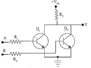
In this setup, the emitter terminals of the transistors are directly linked to the ground terminal. The collector terminals of both transistors are interconnected and connected to the power supply via the 'RC' resistor. This resistor, situated at the collector, is commonly referred to as a passive pull-up resistor in this configuration.
Differences Between Transistors and Variable Resistors in Terms of Working Principle
A critical distinction lies in the linear versus non-linear behavior of resistors and transistors. While resistors exhibit linear characteristics, transistors are non-linear components, evident from their versatile functions. Transistors can function as both switches (resistors) and amplifiers, offering multiple operational capabilities. In contrast, resistors serve a singular core function.
However, a notable similarity between variable resistors and transistors is their ability to vary resistance between collector and emitter currents.
Consider a basic circuit comprising a single bulb, battery, and variable resistor. As you adjust the resistor's control or slide, the intensity of the output current to the bulb either increases or decreases. Consequently, the bulb either dims with increased resistance or brightens with decreased resistance.
Comparison: Trimpot vs. Rheostat – Definitions and Applications
Trimpot Overview:
Trimpots, also known as trimmer potentiometers or pre-set resistors, are compact versions of potentiometers. Adjustment of their resistance typically requires a screwdriver due to their smaller size. They come in various types with different mounting options and adjusting orientations, such as top adjusting orientation with SMD mounting. Trimpots are available as single-turn or multi-turn types, with single-turn trimpots being more cost-effective and multi-turn trimpots offering higher resolution.
Rheostat Overview:
Rheostats, the most prevalent variable resistors, consist of only two terminals or pins, distinguishing them from potentiometers and trimpots. Despite this difference, they serve many similar applications, including current control, dimming light sources, and motor regulation within electrical circuits. Unlike potentiometers, rheostats feature adjustment knobs located on their sides.
Comparison of Transistors and Resistors – Types and Applications
Transistors operate similarly to variable resistors but with the ability to control resistance through current application. Unlike variable resistors that necessitate manual analog switching, transistors often pair with pull-up or pull-down resistors. Various types of transistors find applications in diverse scenarios:
1. Phototransistors: Convert light pulses into digital electrical signals, suited for security systems, readers, infrared detectors, and lighting controls.
2. Bipolar Junction Transistors (BJTs): Serve as switches, filters, rectifiers, oscillators, and amplifiers, widely integrated into cell phones, TV sets, and radio transmitters.
3. Field-Effect Transistors (FETs): Amplify weak signals and are cost-effective to manufacture. Commonly used in testing equipment like voltmeters and oscilloscopes.
4. Darlington Transistors: Feature high electric current gains and remarkable sensitivity, suitable for small devices such as driver chips and push-sensitive buttons.
5. Multi-Emitter Transistors: Specialized bipolar transistors employed in NAND logic gates for specific circuit applications.
How Resistor-Transistor Logic Operates
The functionality of the 2-input RTL NOR gate unfolds as follows: When both inputs, labeled A and B, are at logic 0, insufficient voltage is present to trigger the gate activation of the two transistors. Consequently, the transistors remain inactive, allowing the +VCC voltage to manifest at the 'Y' output terminal. Thus, the output of the circuit registers as logic HIGH or 1 at the 'Y' terminal.
Conversely, if either input is set to logic 1 or a HIGH voltage, the corresponding gate input transistor is activated. This establishes a pathway for the voltage supply to flow to ground through the RC resistor and transistor junction. Consequently, the output of the circuit becomes logic LOW or 0 at the 'Y' terminal.
In the scenario where both inputs receive a HIGH signal, both transistors in the circuit are activated. This facilitates a pathway for the voltage supply to flow to ground through the RC resistor and transistor. As a result, the output of the circuit registers as logic LOW or 0 at the 'Y' terminal. The truth table for the NOR gate is provided below for reference.
Characteristics of Resistor Transistor Logic (RTL):
1. RTL Fan-Out: 5
2. Propagation Delay: 25 ns
3. Power Dissipation: 12 MW
4. Noise Margin for Low Signal Input: 0.4 V
5. Poor Noise Immunity
6. Lower Speed
The distinctions among RTL, DTL, and TTL are as follows:
| RTL | DTL | TTL |
| RTL stands for Resistor transistor logic. | DTL stands for Diode transistor logic. | TTL stands for transistor-transistor logic |
| RTL is designed with transistors and resistors. | It is designed with BJTs, resistors & diodes. | It is built with BJTs & resistors. |
| RTL response is low. | DTL response is better | TTL response is much better |
| RTL power loss is high | DTL power loss is low | Its power loss is very low |
| RTL design is very simple. | Its design is simple. | DTL design is complex. |
| RTL is used in old computers. | DTL is applicable in basic switching & digital circuits. | TTL is utilized in modern ICs and digital circuits. |
| RTL operation is simple | DTL operation is fast | Its operation is substantially slower. |
Advantages and Disadvantages
Advantages of Resistor Transistor Logic (RTL):
- Utilizes minimal transistors for combining input signals, aiding in amplification and inversion.
- Simple and cost-effective RTL gates.
- Convenient availability of both normal and inverted signals.
- Simple design with fewer components, popular in digital electronics.
- Reduces the usage of multiple semiconductor components.
Disadvantages of Resistor Transistor Logic (RTL):
- High current dissipation occurs when transistors overdrive output biasing resistors.
- High power dissipation when transistors are turned on by supplying current through base and collector resistors.
- Limited fan-in capability.
- Slower speed compared to other logic families due to transistor and resistor utilization.
- Complexity of RTL circuits.
- Poor noise immunity leading to vulnerability to signal interference and degradation.
- Requirement for relatively high voltage levels for proper operation, limiting compatibility with other systems.
Applications of Resistor Transistor Logic (RTL):
- Utilized in the Apollo Guidance Computer, showcasing its reliability and importance in critical systems.
- Foundational logic circuits within various digital logic families, demonstrating its widespread use in digital electronics.
- Overview of resistor-transistor logic, a class of digital circuits incorporating resistors and BJTs.
- RTL serves as a primary logic family for ICs, demonstrating its historical significance and importance in early semiconductor technology.
- Logic gates employing RTL technology primarily utilize resistors and NPN transistors, leveraging resistors as current limiters and NPN transistors as switches.
Related Articles
10k Resistor Color Code: Everything You Need to Know
Is a Fuse a Resistor? [Everything Explained]
Wirewound Resistor: An In-Depth Overview


