


How Does a Voltage Regulator Work? [Completely Explained]

How Does a Voltage Regulator Work
Regardless of load current and input voltage, voltage regulators maintain the system's output voltage. In this article, I am going to discuss “how does a voltage regulator work” and its design, construction and much more with you. To ensure the safety and stability of your electronics, understand how these regulators work, including their switching topologies. This comprehensive guide is ideal for engineers or anyone who wants to learn more about voltage regulation.
What Is a Voltage Regulator?
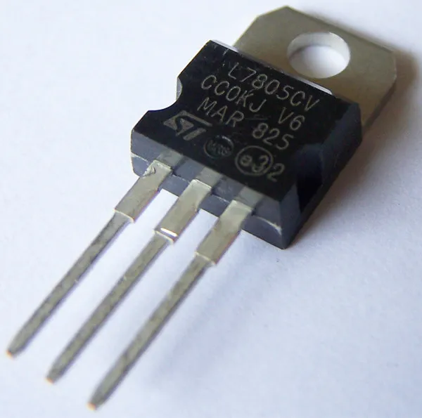
Voltage Regulator
Using a voltage regulator, voltage levels can be regulated. Voltage regulators are the best device for maintaining a steady, reliable voltage. Regardless of the input voltage or load conditions, it generates a constant output voltage. It protects components from damage by acting as a buffer. Voltage regulators operate using negative feedback controls and have simple feed-forward designs.
An output voltage that is more stable and lower than the input voltage is generally produced by regulators. Furthermore, they act as a shield against voltage surges that could damage or fry the circuit.
Current and voltage are both electrical instruments designed to work at fixed power ratings. Despite current usage being dynamic and dependent on device load, a voltage supply should be set and preferably constant for the device to operate properly. Regulators are responsible for maintaining the system's optimal voltage. Laptops, wall adapters, and coffee machines are all compatible with both of them due to their voltage regulators.
How Does a Voltage Regulator Work?
In a voltage regulator, output voltage is compared to a reference voltage before output is calculated. In this case, the regulation element boosts the variation in order to lower the voltage error. Regulation precision is usually improved by increasing open-loop gains, but stability is typically decreased. Control is negatively influenced by it. The definition of stability is to avoid oscillations during step changes. Also, response time and stability will be traded off to achieve stability. Do you want to learn more about how does a voltage regulator work? If yes, then don't stop here and continue reading!
Input voltage is lowered less or input current is drawn longer, in order to generate a higher output voltage. The regulation element often produces a lower value if the output voltage is too high. There are also overcurrent protections available on many regulators that can stop the output current when there is a significant level of output current. There are a variety of regulators that may shut down when the input voltage exceeds a certain level.
You want to know how does a voltage regulator Work? Then the first step in creating an electronic voltage/current regulator is by connecting a resistor and a diode in series. Since diode V-I curves are logarithmic, the voltage across the diode is not affected by changes in input or current draw. In the case of non-critical variables, such as voltage control and energy efficiency, it may be an option. Voltage regulators of this type are specifically designed for low voltage-controlled outputs, since diodes have relatively low forward voltages. In order to achieve a greater voltage output, several Zener diodes can be used or one Zener diode alone. A Zener diode regulator uses its fixed reverse voltage, which can be extremely high.
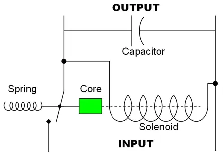
Electromechanical voltage regulator circuit design
Electromechanical regulators efficiently and effectively regulate voltage by coiling sensor wires to create electromagnets. Moving ferrous cores are drawn to the magnetic field created by the current, which is held back by spring tension or gravitation. Voltage and current increase in the coil, increasing the magnetic field, attracting the core. Mechanical power switches attached directly to the magnet open as soon as it enters the field. A rising voltage releases tension from a spring or core by lowering voltage and current. Thus, power is restored by shutting off the switch.
By using a high-voltage resonant winding and a capacitor, constant voltage-transformers produce almost constant output voltages with fluctuating input currents. There are three coils in a shunt: a primary coil, a tuned coil, and a secondary coil. The regulation occurs because of magnetic saturation around the secondary. As a result of its lack of active components, ferroresonant circuits are attractive because they can absorb changes in the average input voltage due to their square loop saturation properties. I hope after reading this section which is about “how does a voltage regulator work”, your confusion got cleared. If you have any, then you can comment below. So without wasting more time, let's discuss the voltage regulator types.
Types of Voltage Regulators
Series Voltage Regulators
Voltage regulators in series use a variable element connected to the load in series. Voltage dropped across that series element can be changed by changing its resistance. Throughout the load, there is a constant voltage. The main advantage of a series voltage regulator is that the load effectively uses the current drawn. The series regulator doesn't draw full current even when there is no load. This results in a much lower efficiency in shunt voltage regulators than in series voltage regulators.
Switching Voltage Regulators
Series devices are switched on and off rapidly by a switching regulator. Charge transferred to the load will vary depending on the duty cycle of the switch. Feedback is used to control this, similar to a linear regulator. Series regulators dissipate almost no power since all or almost all of the series elements are conducting. The output voltages of switching regulators are higher than those of linear regulators, or they can have the opposite polarity from the input voltage.
Voltage regulators switch quickly on and off to change output. Control oscillators and storage components are also required. Filtering out those noises in a switching regulator is more difficult due to Pulse Rate Modulation's changing frequency, constant duty cycle, and noise spectrum. Pulse Width Modulation (PWM), varying duty cycle and constant frequency are efficient and noise-free switching regulators.
An inductor's continuous mode current will never drop to zero when connected to a switching regulator. Highest power output is possible with it. Performance has improved.
Transistor Voltage Regulator
The Zener diode, also known as reverse breakdown voltage operating diode, provides an astable voltage reference source for electronic voltage regulators. Despite changes in the input voltage, the output voltage remains constant. There is a block on AC ripple voltage, but there is no block on AC filter voltage. As well as short circuit and current limiting protections, overvoltage protection, and thermal shutdowns, the voltage regulator includes circuitry to protect it from damages.
Shunt Voltage Regulators
With a shunt voltage regulator, voltage is supplied through a variable resistance to ground. As the current flows uselessly to the ground in a shunt regulator, it is less efficient than its equivalent in a series regulator since the current has been diverted away from the load. In low-powered circuits, a voltage-reference diode is sometimes sufficient, in which case the wasted current is not of concern. Voltage reference circuits usually take this form. Current can only be absorbed (sunk) by a shunt regulator.
Linear Voltage Regulators
Linear regulators divide voltages. An Ohmic FET is used in this region. A voltage regulator produces a constant output voltage by varying its resistance with load. Power supplies were originally regulated by linear voltage regulators. MOSFETs and BJTs are active pass elements which are responsible for varying the output voltage in this type of regulator.
A transistor's output will remain constant no matter what changes in input or load are made once a load is allied, despite changes in input or load. When working in an active region, transistors can change their current. Due to the voltage drop within the transistor during this process, this regulator dissipates a huge amount of power.
How to Choose the Correct Voltage Regulator?
If you read the “how does a voltage regulator work” part, then make sure to read this one too. Before buying the regulator, it's important to know which one to choose for you. So without wasting more time, let's get started:
Designers take into account key parameters like Vin, Vout, Iout, system priorities, etc., when selecting a voltage regulator. Additional features, such as controlling the power or indicating that the power is in good condition.
To find the best apparatus that meets up the designer's preferred requirements, utilize a parametric search table.
There are a number of features and packages available in this table that make it very useful for designers since they can meet both the requirements for their job as well as the specified parameters.
To obtain a high-performance, stable, efficient design, MPS devices come with datasheets describing in detail the requirements of the external components.
The output can be measured in terms of inductance, resistivity, and capacitance using this datasheet.
Faqs
Question 1: How does an automatic voltage regulator work?
Answer: By stabilizing the output voltage of generators at variable loads (voltage droop), automatic voltage regulators (AVRs) can also help the generator respond to overloads and divide the reactive load between parallel generators.
Question 2: Does voltage regulator output DC or AC?
Answer: In order to maintain a steady, constant voltage supply, voltage regulators regulate AC as well as DC voltages. Voltages from the input are usually higher than voltages from the output. Regulators adjust output voltage based on voltage comparisons with reference voltages.
Question 3: How does a voltage regulator control alternator output?
Answer: Voltage regulators sense output voltage and current as you wind stator coils. The rotor field current is usually adjusted to maintain the voltage. Limiting the output current requires cutting back the field current when the output current is excessively high.
Final Thoughts
The purpose of this article is to explain how voltage regulators work and the types of voltage regulators available. For a better understanding of how voltage regulators work, we hope that the information provided in this article about "How Does a Voltage Regulator Work" is helpful. Furthermore, you can reach us in the comment section below if you have any questions about this article or need assistance with electrical and electronics projects. Let me ask you this question - Where will we use an alternator voltage regulator? Make sure to let me know in the comment section. Thank You!


