


Explanation of the Working Principle of Photodiodes
What is a Photodiode?
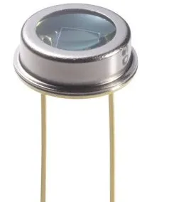
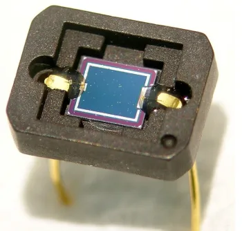
A photodiode is a semiconductor device that converts light into current. It consists of an intrinsic layer between the p (positive) and n (negative) layers. Photodiodes accept light energy as input to generate current. They are also referred to as photodetectors, photo sensors, or light detectors.
Photodiodes operate under reverse bias conditions, meaning the p-side of the photodiode is connected to the negative terminal of a battery (or power supply), while the n-side is connected to the positive terminal of the battery. Typical materials for photodiodes include silicon, germanium, indium gallium arsenide phosphide, and indium gallium arsenide.
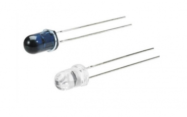
Internally, a photodiode features a filter, built-in lens, and surface area. Increasing the surface area of a photodiode shortens its response time. Photodiodes rarely resemble light-emitting diodes (LEDs). They have two terminals, as follows: the smaller terminal serves as the cathode, while the longer terminal serves as the anode.
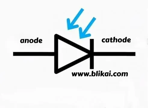
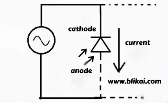
The pictorial symbol for a photodiode
The symbol for a photodiode is similar to that of an LED, but with the arrow pointing inward instead of outward as in an LED. The diagram below illustrates the symbol for a photodiode.
Principle of Operation of Photodiode
The principle of operation of a photodiode is that when a sufficiently energetic photon strikes the diode, it generates an electron-hole pair. This mechanism is also known as the internal photoelectric effect. If absorption occurs within the depletion region junction, the carriers are removed from the junction by the built-in electric field of the depletion region.
Usually, when the PN junction is illuminated, covalent bonds are ionized. This generates electron-hole pairs, resulting in photocurrent. When photons with energy greater than 1.1eV strike the diode, electron-hole pairs are formed. As photons enter the depletion region of the diode, they impact the atoms with high energy, leading to the release of electrons from the atomic structure. After the electrons are released, free electrons and holes are generated.
Generally, electrons carry negative charge, while holes carry positive charge. Depletion results in a built-in electric field. Due to this field, electron-hole pairs are pushed away from the PN junction. As a result, holes move towards the anode, and electrons move towards the cathode to generate photocurrent.
The intensity of photon absorption is directly proportional to the photon energy. The lower the photon energy, the more absorption occurs. This entire process is known as the internal photoelectric effect.
Intrinsic excitation and extrinsic excitation are two methods of photon excitation. In the intrinsic excitation process, electrons in the valence band are excited to the conduction band by photons.
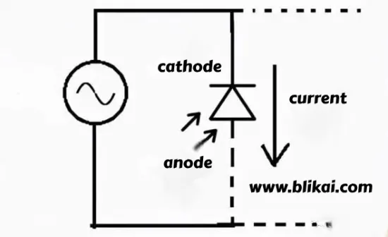
The working circuit of a photodiode
Photodiodes primarily operate in three different modes:
1. Photovoltaic mode
2. Photoconductive mode
3. Avalanche photodiode mode
Photovoltaic mode
The photovoltaic mode, also known as zero bias mode, is preferred when photodiodes are used in low-frequency applications and super-level light applications. In this mode, when the photodiode is illuminated, it generates a voltage. The generated voltage has a very small dynamic range and exhibits nonlinear characteristics. When configured with an OP-AMP in this mode, the photodiode's response to temperature changes will be minimal.
Photoconductive Mode
In the photoconductive mode, the photodiode operates under reverse bias conditions, with the cathode as the positive terminal and the anode as the negative terminal. As the reverse voltage increases, the width of the depletion layer also increases. Consequently, the response time and junction capacitance decrease. This operational mode is faster but generates electron noise.
Avalanche Photodiode Mode
Avalanche photodiodes operate under high reverse bias conditions, allowing avalanche breakdown to multiply for each electron-hole pair generated by light. The result is internal gain in the photodiode, which gradually increases device response.
Photodiode Circuit
The circuit diagram for a photodiode is shown below. This circuit can be constructed using a 10k resistor and a photodiode. Once the photodiode detects light, it allows some current to pass through it. The sum of the currents provided by the diode can be directly proportional to the total amount of light observed by the diode.
Connecting a Photodiode in an External Circuit
The photodiode operates in a circuit with reverse bias. The anode is connected to the circuit ground, while the cathode is connected to the positive power supply voltage of the circuit. When illuminated by light, current flows from the cathode to the anode.
When used in conjunction with an external circuit, photodiodes are connected to the power supply of the circuit. The amount of current generated by the photodiode will be very small. This current is insufficient to drive electronic devices. Therefore, when connected to an external power source, it provides additional current to the circuit. Consequently, batteries are used as power sources. The battery source helps increase the current value, aiding external devices to perform better.
Manufacturing Process of Photodiodes
Materials for Photodiodes
The materials of a photodiode determine many of its characteristics. Key features include the wavelength of light to which the photodiode responds and the level of noise, both of which depend largely on the materials used in the photodiode.
Different materials lead to different responses to wavelengths because only photons with sufficient energy can excite electrons in the material's bandgap, producing significant energy to generate current from the photodiode.
While the wavelength sensitivity of the material is crucial, another parameter that can significantly impact the performance of photodiodes is the level of noise generated.
Due to its larger bandgap, silicon photodiodes generate less noise compared to germanium photodiodes. However, consideration also needs to be given to the wavelength required for the photodiode, and germanium photodiodes must be used for wavelengths longer than approximately 1000 nm.
Structure of Photodiodes
One of the key requirements for photodiodes is to collect light in the appropriate area. Within the standard PN junction, this area is relatively small, but it can be increased by using a PIN diode. Since the intrinsic region is contained within the active region used for light collection, the area for light collection needs to be much larger, making PIN photodiodes more effective.
In the manufacturing process of photodiodes, a thick intrinsic layer is inserted between the P-type and N-type layers. This intermediate intrinsic layer can be either fully intrinsic or very lightly doped to make it an N- layer. In some cases, it can be grown as an epitaxial layer onto the substrate, or it can be contained within the substrate itself.
The development of P+ diffusion layers can be done on heavily doped N-type epitaxial layers. Contacts are designed using metals to form two terminals such as an anode and a cathode. The front area of the diode can be divided into two types, such as active surface and non-active surface.
The design of the non-active surface can be achieved using silicon dioxide (SiO2). On the active surface, light can be irradiated, while on the non-active surface, light cannot be irradiated. By covering the active surface with anti-reflective materials, the energy of light is not lost and can be converted into current, maximizing its conversion efficiency.
One of the primary requirements for photodiodes is to ensure the maximum amount of light reaches the intrinsic layer. One of the most effective ways to achieve this is by placing the electrical contacts on the side of the device, as shown in the diagram. This allows the maximum amount of light to reach the active area. Since the substrate is heavily doped and not an active region, there is minimal light loss.
Because most of the light is absorbed within a certain distance, the thickness of the intrinsic layer is typically matched to this. Any increase in thickness beyond this will decrease the operating speed—a critical factor in many applications—without significantly improving efficiency.
It's also possible to allow light to enter the photodiode from the side of the junction. Operating the photodiode in this manner can reduce the thickness of the intrinsic layer to improve operating speed, albeit with a decrease in efficiency.
In some cases, heterojunctions can be used. This structural form offers additional flexibility, allowing light to be received from the substrate and having a larger bandgap, making it transparent to light.
As a less conventional process, its implementation cost is higher, so it is often used for more specialized products.
Photodiode Characteristics
IV Characteristics
The IV characteristics refer to the relationship between the photocurrent on the photodiode and the voltage applied to it.
Illumination Characteristics
Illumination characteristics refer to the relationship between the light flux and the photocurrent when the voltage across the cathode and anode of the photodiode is constant. The slope of the illumination characteristic curve is called the sensitivity of the photodiode.
Spectral Characteristics
Spectral characteristics refer to the relationship between the photocurrent and the wavelength of incident light. Photon energy is related to the wavelength of light: the longer the wavelength, the smaller the photon energy; the shorter the wavelength, the larger the photon energy.
Functions and Applications of Photodiodes
Functions of Photodiodes
Photodiodes are widely used in:
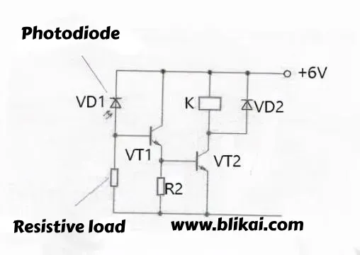
1. Light Control
Photodiodes can be used as photoelectric switches, as shown in the circuit diagram below. When there is no light, photodiode VD1 is in the off state due to reverse voltage. Transistors VT1 and VT2 are also in the off state due to no base current. The relay is in the release state.
When light is emitted onto VD1, it transitions from off to on. As a result, VT1 and VT2 turn on sequentially, the relay K closes, and the control circuit is activated.
2. Light Signal Reception
Photodiodes can be used for receiving light signals. The circuit diagram below illustrates a circuit for amplifying light signals received by a photodiode. The light signal is received by the photodiode VD, amplified by the transistor VT, and outputted through coupling capacitor C.
VI. Applications of Photodiodes
Specific applications of photodiodes include:
1.Phototubes
Phototubes are essentially large-area PN junctions. When light is emitted on one surface of a PN junction, such as the P-region surface, if the photon energy is greater than the bandgap width of the semiconductor material, each photon in the P-region generates a free electron-hole pair.
2. Solar Cells
Solar cells are semiconductor devices. When sunlight shines on a semiconductor, some of it is reflected, while the rest is absorbed or transmitted through the semiconductor.
Some of the absorbed light turns into heat, while other photons collide with the valence electrons that make up the semiconductor, generating electron-hole pairs. Thus, solar energy is converted into electrical energy.
Therefore, after sunlight irradiation, solar cells generate direct current voltage at both ends, thus directly converting solar energy into direct current. If we solder metal leads to the P-layer and N-layer and connect a load, current will flow through the external circuit.
By connecting photodiodes in series and parallel, we can generate a certain voltage and current, thereby outputting power.
3. Photovoltaic Power Generation Lighting System
A photovoltaic power generation system is a power generation system that converts solar energy into electrical energy using solar cells. It exploits the photovoltaic effect.
The main components are solar cells, batteries, controllers, and inverters. It has high reliability, long service life, no pollution, independent power generation, and photodiodes operate in grid-connected mode.
As the photovoltaic mode of photodiodes is greatly affected by external environmental factors such as light and temperature, the operating point changes rapidly. There are independent power generation systems and grid-connected power generation systems.
(1) Independent Photovoltaic Power Generation System
An independent photovoltaic power generation system is a power generation method that is not connected to the grid. It requires batteries to store energy for nighttime use. Independent solar photovoltaic power generation is mainly used in remote villages and households.
(2) Grid-connected Photovoltaic Power Generation System
Grid-connected photovoltaic power generation systems are connected to the national grid to supply power. They do not require batteries. Residential photovoltaic power generation systems are mostly used in households. They are also used in public facilities, nighttime landscape lighting systems, and solar farms.
Other applications of photodiodes include:
Used as photodetectors in light sensors. Since the current in them is proportional to the intensity of light, they are also used to measure light intensity.
Photodiodes in smoke detectors can be used to sense smoke and fires.
Photodiodes are used in conjunction with LEDs to make opto-isolators and opto-couplers.
Used in solar panels as solar cells.
Used in barcode scanners, character recognition systems.
Used in obstacle detection systems.
Can be used in printers as page presence and page counters.
Used in proximity detection, pulse oximeters.
It is also used in optical encoders and decoders.
Optical information transmission, based on fiber optic communication.
Position sensors.
Photodiode Selection Parameters
There are four main parameters used to select the right photodiode and whether to bias it in reverse:
1. Dark Current
Dark current is the current through the photodiode when there is no light in photovoltaic mode. Dark current in the photodiode includes the radiation current and saturation current of the semiconductor junction. It must be measured in advance. Especially in precision optical power measurements, errors caused by dark current must be carefully considered and corrected.
2. Photodiode Response Time
Response rate is the ratio of photodiode current in photovoltaic mode to incident light power, expressed in A/W. Response characteristics can also be expressed as the quantum efficiency of the photodiode, i.e., the ratio of the number of carriers generated by light to the number of incident photons.
3. Noise Equivalent Power (NEP)
Noise equivalent power refers to the minimum optical power required to generate photocurrent, which equals the RMS noise power at 1 Hz. It is approximately equal to the minimum detectable input power of the photodiode. A related attribute is the detectivity (D), which is the reciprocal of the noise equivalent power.
4. Frequency Response Characteristics
Mainly determined by three factors:
(1) Diffusion time of photo-generated carriers near the depletion layer;
(2) Drift time of photo-generated carriers in the depletion layer;
(3) Circuit time constant determined by the load resistor and parallel capacitor.
Other important parameters include material, size of the photodiode and active region, as well as cost. Careful consideration is needed when procuring photodiodes.
Photodiodes made from different materials (such as silicon, germanium, indium gallium arsenide phosphide, or indium gallium arsenide) have different levels of sensitivity as well as different speeds and dark currents. For example, silicon provides sensitivity to wavelengths ranging from about 400 to 1000 nm. However, it has the highest sensitivity at higher wavelengths (~900 nm).
On the other hand, germanium provides sensitivity to wavelengths between about 800 and 1600 nm (with a peak around 1400 nm).
How to Test a Photodiode for Good or Bad?
1. Resistance Measurement Method
Use a multimeter's "1k" setting to test the photodiode. The forward resistance of a photodiode is approximately 10 kΩ.
When there is no light, if the measured reverse resistance is ∞, then the diode is good, or there may be a significant leakage current.
When there is light, the reverse resistance decreases with increasing light intensity. If the resistance can reach several kΩ or is below 1 kΩ, the diode is good. If the reverse resistance is ∞ or zero, then the diode is damaged.
2. Voltage Measurement Method
Use the multimeter's "1V" range. Connect the red probe to the photodiode's anode and the black probe to the cathode. Under illumination, the voltage is proportional to the light intensity and generally ranges from 0.2V to 0.4V.
3. Short Circuit Current Measurement Method:
Use the multimeter's "50 μA" range. Connect the red probe to the photodiode's anode and the black probe to the cathode. Under an incandescent lamp (not a fluorescent lamp), if the short-circuit current increases with increasing light, then the diode is good. The short-circuit current can range from tens to hundreds of microamperes.
Sometimes it's necessary to differentiate between infrared emitting diodes (IREDs) and infrared photodiodes.
If they are both encapsulated in transparent resin, we can observe their molds. In an infrared LED, there is a shallow plate beneath the LED chip, but in an infrared photodiode, there is no such plate beneath the chip.
If it is a small-sized photodiode or it is packaged in black resin, you can use a multimeter (set to the 1k range) to measure resistance.
First, ensure the diode is not exposed to light. If the measured forward resistance is 20-40kΩ, and the reverse resistance is greater than 200kΩ, then the forward resistance is approximately 10kΩ and the reverse resistance is close to ∞, indicating a photodiode.


