


Current Transformers:Princeple,Types,Application and FAQ
Current transformers (CTs) are instruments based on the principle of electromagnetic induction, used to convert high primary currents into lower secondary currents for measurement purposes. They typically consist of a closed iron core and windings. The primary winding, with a small number of turns, is connected in series with the circuit carrying the current to be measured. Thus, the full current of the circuit often passes through the primary winding. The secondary winding, with a larger number of turns, is connected in series with measuring instruments and protection circuits.
What are current transformers and their functions?
Current transformers are utilized to transform large currents into proportionally smaller currents, making them suitable for protection and measurement applications. For instance, a current transformer with a ratio of 400/5 transforms 400A of current into 5A. Additionally, current transformers are essential for monitoring and measuring the operation of electrical equipment to ensure the safety and efficient operation of power systems.
How do I choose the right current transformer?
Firstly, consider the size of the current transformer. There are typically two types: round-hole and square-hole. Round-hole CTs are used for cables, while square-hole CTs are used for busbars. Determine the specifications of the cable or busbar to select the appropriate CT aperture size to avoid installation issues.
Secondly, determine the range of current at the site to select the appropriate transformation ratio. The CT ratio should be slightly larger than the rated current.
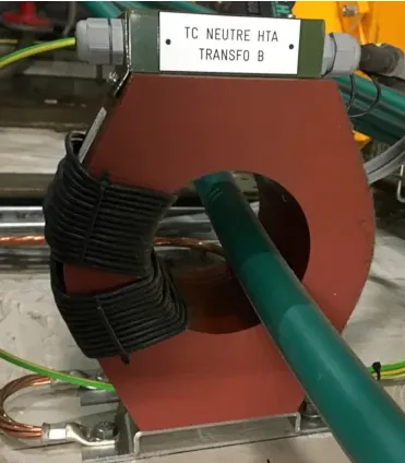
Consider the installation conditions at the site. For new projects, closed-core CTs can be chosen. For retrofitting or replacement projects where disconnecting lines is inconvenient, open-core CTs can be chosen. They are easily installed by opening the clasp and clipping onto the cable without requiring power interruption or line disconnection.
Depending on the application, current transformers can be broadly classified into two types:
Measurement CTs: Provide information about the current of the power grid to measuring and metering devices within the normal operating current range.
Protection current transformers (CTs) are instrumental in relaying fault current information from the power grid to relay protection devices during grid fault conditions.
The accuracy limit factor is a crucial parameter for protection CTs. It signifies the saturation properties of the core when exposed to high primary currents, impacting its capacity to precisely represent the primary current.
How to Interpret Current Transformers
Understanding the Transformer Ratio
Current transformers (CTs) operate similar to transformers and their transformation ratio is correlated with the number of turns on the primary and secondary sides. Adjusting the number of turns on the primary side of a CT alters the transformation ratio of the CT, considering that the secondary output of a CT is typically 5A.
Interpreting the Label
For instance, if the label on a CT indicates "50/5 A", when installing, winding the primary side three times will achieve a transformation ratio of 50/5. Winding it twice corresponds to 75/5, and winding it once (core installation) corresponds to a specification of 150/5.
Usage Guidelines for Current Transformers
Wiring Principles
Follow the series connection principle when wiring current transformers: connect the primary winding in series with the circuit to be measured, and connect the secondary winding in series with all instrument loads.
Selection Based on Current
Select a suitable transformation ratio based on the measured current to prevent an increase in errors. Additionally, one end of the secondary side must be grounded to prevent accidents in case of insulation damage, preventing high voltage from the primary side from entering the low-voltage secondary side.
No Open Circuits on the Secondary Side
Under no circumstances should the secondary side be open-circuited. Otherwise, all primary current will be converted into magnetizing current, leading to saturation and overheating of the core, which could result in coil burnout.
Installation Requirements
Install 2 to 8 current transformers (CTs) in various circuits, including generators, transformers, outgoing lines, bus section circuit breakers, bus circuit breakers, and bypass circuit breakers. This installation facilitates the requirements of measuring instruments, relay protection, circuit breaker malfunction detection, and fault filtering devices.
Placement for Protection CTs
Place protection CTs at locations that minimize unprotected areas of the main protection device. For instance, if there are two sets of CTs and the location permits, they should be placed on either side of the circuit breaker to ensure it falls within the cross-protection range.
Preventing Insulation Flashover
To prevent bushing-type CT flashovers causing busbar faults, CTs are usually arranged on the outgoing line or transformer side of the circuit breaker.
Location in Power Generation Systems
To reduce damage in case of internal faults in generators, CTs used for automatic excitation regulation should be placed on the outgoing line side of the generator stator winding. For easy analysis and detection of internal faults before the generator is connected to the system, CTs used for measuring instruments should be installed on the neutral point side of the generator.
The Turns Ratio of Current Transformers
Current transformers (CTs) are primarily used to change voltage values. However, as a secondary effect, they also modify current values.
Step-up transformers reduce the current in the secondary winding, while step-down transformers increase the current in the secondary winding to maintain the power entering the transformer equal to the power leaving it. Certain transformers are engineered to modify current values; these are referred to as current transformers. Typically, current transformers step down high currents to levels appropriate for metering purposes—for instance, converting a 500 ampere current in a distribution panel to a 1 ampere current compatible with a current meter.
The Turns Ratio of Current Transformers
Based on the principle of transformer action:
To ensure that the secondary current is less than the primary current, the secondary voltage must be higher than the primary voltage, and the number of turns in the secondary winding will be greater than that in the primary winding. Large primary currents, such as 500 amperes, would necessitate excessively large primary windings. Therefore, current transformers use the primary conductor itself as the primary winding.
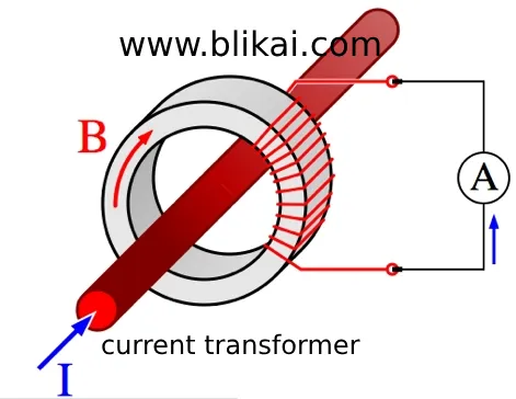
When a single wire is used as the primary of the transformer, there is one turn in the primary winding. Since the primary of the current transformer is the power conductor itself, the current transformer consists only of the secondary winding. The magnetic flux generated by the current flowing in the power conductor passes through the large number of secondary winding turns wound around the primary conductor. Diagram 1 depicts an example of a current transformer. The secondary winding is composed of numerous small wire turns encapsulated in epoxy resin or other insulating materials.
Types of Current Transformers
There are three main types of current transformers
Solid-Core Current Transformers
These have a single secondary winding forming a solid ring or toroid that passes over the primary conductor before being terminated.
Split-Core Current Transformers
These have a single secondary winding designed to be split apart and placed around the already-terminated primary conductor. Clamp-on current meters are a type of split-core current transformers; they are opened and encircled around the conductor to gauge the current flow in amperes.
Bar-Type Current Transformers
The secondary winding is already wound around a bar. The primary conductor is fastened to the bar's ends with bolts, and the current then flows through the bar.
Current Transformer Current and Voltage Ratio
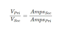
The transformation ratio of a current transformer reflects the current value, not the voltage value. For most current transformers, the ratio is such that the maximum secondary current is 5 amperes; for example, 100:5 (100 amperes to 5 amperes), which means the turns ratio is 1:20, as the transformer current is inversely proportional to the voltage. Hence, an 80-amp current passing through the primary conductor will lead to a 4-amp reading on the external ammeter.
The ammeter or measuring instrument establishes the necessary secondary current rating. In all cases, the magnetic flux from the primary conductor passes through a large number of turns in the secondary winding, inducing a higher secondary voltage and corresponding lower secondary current. For instance, with a transformer ratio of 500:5 and a turns ratio of 1:100, if the primary current is 300 amperes, the secondary current would be:
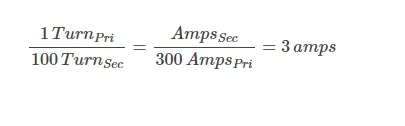
Finding an ammeter capable of measuring 5 amperes or less is quite easy. Simply changing the scale of the ammeter from 3 amperes to 300 amperes will reflect the actual amperage of the circuit.
The voltage ratio is the reciprocal of the current ratio, which in our example is 5:500.If the primary voltage measures 240 volts, then the resultant secondary voltage corresponds to:
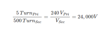
As evident, the secondary voltage level may appear considerable, leading to a significant potential disparity across the ammeter's terminals. However, as long as the current traverses the secondary of the current transformer, there exists ample counter-electromotive force (CEMF) to offset the secondary voltage, maintaining it at a substantially lower magnitude. This mechanism serves to constrain the emergence of excessive excitation current in the primary of a standard transformer.
The Danger of Open Circuits in the Secondary Conductor
If the secondary conductor of the transformer is no longer connected to the load, there will be no secondary current or CEMF.Moreover, the secondary voltage may surge to exceedingly high levels, posing a risk of breaching the insulation of the secondary conductor and precipitating a short circuit, consequently jeopardizing the integrity of the current transformer. Therefore, the secondary winding must always have current flowing through it as long as there is current flowing through the primary winding.
Attention: To prevent damage to the current transformer, the secondary winding must never be disconnected from its load when current is flowing through the primary conductor. Before disconnecting any load or if no load is connected to the secondary of the current transformer, the secondary conductor must be short-circuited together.
Polarity of Current Transformers
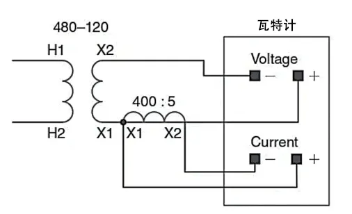
Current transformers, like ordinary transformers, have polarity. During the installation of a current transformer, it is imperative that the H1 side is oriented towards the power source. When the current enters the primary winding at H1, the current from the secondary winding at X1 will also be positive and proportional to the primary current. The H1 and X1 terminals are usually marked with dots to indicate the same polarity. Correct polarity is essential for instruments to accurately measure and display values. The chart in Figure 2 shows the symbol of a current transformer with polarity markings. The power conductors should be connected to the corresponding polarity terminals on the wattmeter as the current transformer. When the same polarity is connected to the correct terminals, voltage and current are in phase, and the wattmeter reads correctly.
Key Points of Current Transformers
A comprehensive understanding of current transformers is crucial for professionals in the electrical field. Proficiency in understanding their functions, types, and operating principles is essential to ensure accurate measurement, maintain equipment integrity, and prevent potential hazards. It's crucial to have a thorough understanding of current transformers and to handle them correctly, particularly to mitigate risks related to open-circuit secondary conductors. These can lead to extremely high voltages and insulation breakdown, posing significant risks to equipment and personnel. Therefore, understanding current transformers is essential for efficient power distribution, measurement, and ensuring electrical system safety.
Final Thoughts
This article introduces the definition and characteristics of current transformers, as well as their important role in converting large currents into small currents. It encompasses factors such as winding ratio, different types, and the significance of preserving measurement polarity.
Related Articles
What are Audio Transformers for?
Transformer Core Faults: Hazards, Causes, Types, Testing, and Remediation
SN6505BDBVR Transformer Driver: Features, Application and Datasheet


